
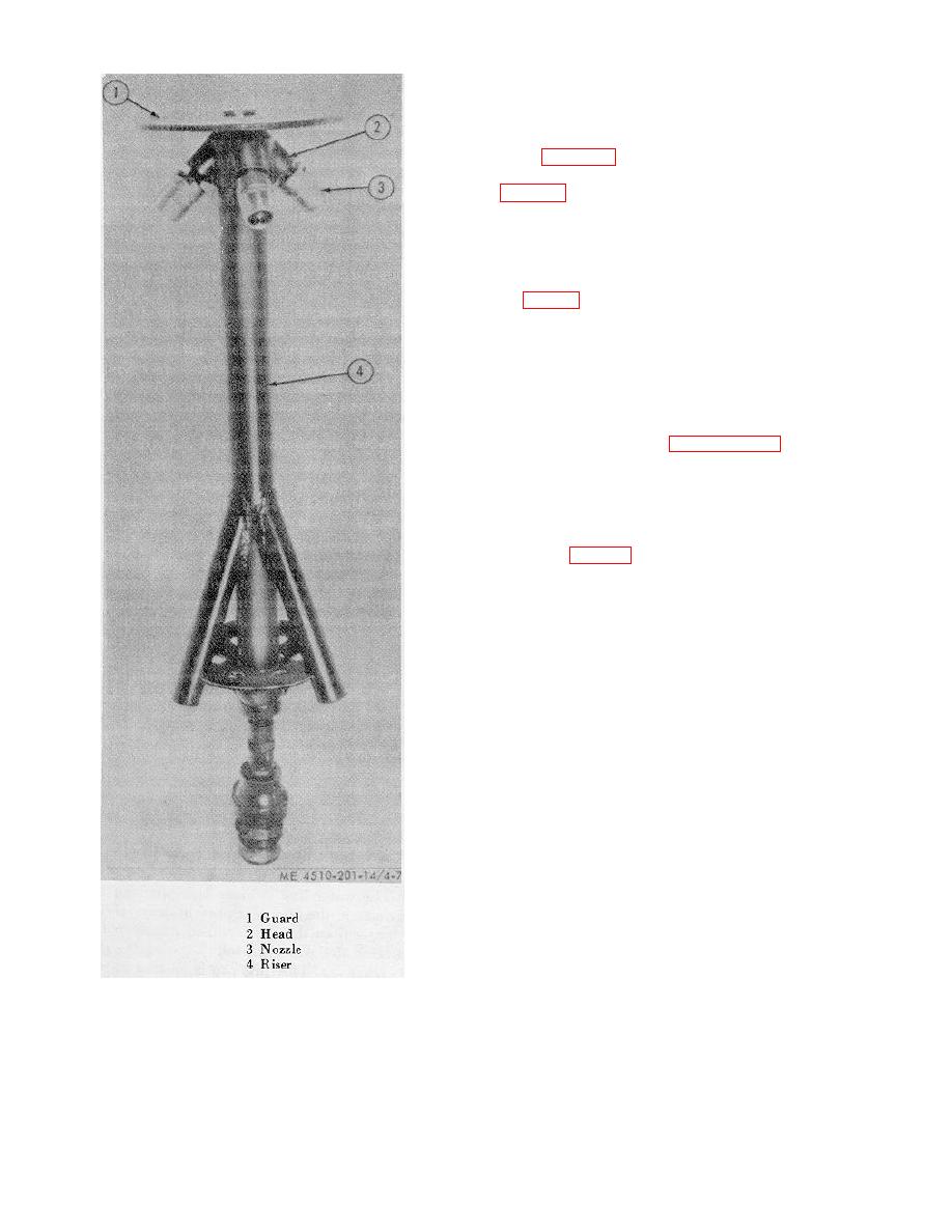
4-20. Riser
a. Removal.
(1) Remove the shower stand head from the
riser (para 4-19c(2)).
(2) Remove the upper reducing coupling (1,
Coupling is used on Army models SPE 41, SPE 44,
SPE 45 and York-Shipley Model YS49279.
(3) Unscrew and remove the adapter from the
riser (On Army models SPE 35 and SPE 35A).
(4) Pull the shower stand legs from the riser
(4, fig. 4-7).
b. Inspection. Inspect for dented and broken riser.
Inspect the riser and the soap tray for clogged openings.
Make certain that leg sockets are not dirty. Check welds
for cracks or breaks.
c. Installation. Replace defective riser with a
serviceable one, and install it by reversing the
procedure in a above.
Nipples (Used on Army Models SPE 41, SPE 44, SPE
45 and York-Shipley Model YS49279)
a. Description. The shower stand flow control
valve (3, fig. 4-8) is located at the bottom of the riser
between the two reducing couplings (1 and 5). It
restricts or controls the amount of water flowing to the
shower head, thereby allowing the shower spray to
remain constant.
b. Removal.
(1) Unscrew and remove the adapter (6) from
the lower reducing coupling (5).
(2) Unscrew and remove the reducing
coupling from the lower pipe nipple (4).
(3) Unscrew and remove the lower nipple
from the flow control valve (3).
(4) Unscrew and remove the flow control
valve from the upper pipe nipple (2).
(5) Unscrew and remove the upper pipe
nipple (2) from the upper reducing coupling (1).
(6) Unscrew and remove the reducing
coupling from the shower stand riser.
c. Inspection.
Inspect for bent or cracked
couplings and nipples, and inspect for damaged threads
on the couplings and nipples.
d. Installation. Replace defective couplings, flow
control valve and nipples with serviceable ones. Install
them by reversing the procedure in b above, making
certain the flow control valve is installed with the arrow
pointing in the direction of the flow of water.
