TM 10-3510-209-24
2-21.1. WASHER FLOAT LEVEL ASSEMBLY
This task covers:
a. Inspection
c. Disassembly
e. Installation
b. Removal
d. Repair
f. Adjustment
INITIAL SETUP
Tools
General Safety Instructions
General mechanic's tool set,
SC 5180-90
WARNING
High voltage is present on this equipment. Do not perform
Personnel Required
maintenance with power on. Death or serious injury may result.
MOS 63J (1)
Equipment Conditions
Materials/Parts
TM 10-3510-209-10, Water drained from washer.
TM 5-6115-585-12, Generator off.
TM 10-3510-209-10, Water pump removed.
Paragraph 2-22, Washer drivebelt cover removed.
INSPECTION
Inspect for cracks, freeze breaks, loose fittings,
damaged hose or incorrect float operation.
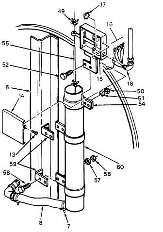
REMOVAL
a.
Remove screw (13) and cover (14) from
float switch (15).
2.
Tag and disconnect wires (16) and remove nut
(17) from electrical cable (18). Remove electrical cable
from float switch (15).
3.
Loosen clamp (7) to remove tube (8) from float
chamber (60).
4.
Remove four bolts (58), nuts (56) and washers
(57) from support brackets (59).
5.
Remove float chamber (60) from washer
assembly (6).
DISASSEMBLY
1. Remove low-level speednut (49) from float rod
(55) by pinching speednut ends together.
2.
Remove hex nut (50), lock washer (51) and
screw (52) from float switch assembly (15) and float
chamber clamp (54).
3.
Remove float switch assembly (15) from float
rod (55).
4.
Remove float rod (55) from float chamber (60).
2-84 Change 1