TM 10-3510-220-24
2-29. EXTRACTOR ASSEMBLY (CONT)
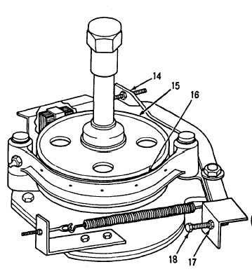
ADJUSTMENT
1. Adjust brake shoe.
a.
b.
c.
d.
e.
f.
g.
h.
N O T E
High voltage is present on this equip-
ment. Do not perform maintenance
with power on. Death or serious injury
may result.
Remove access plate (See SERVICE, step 1).
Loosen brake adjusting locknut (17).
Adjust brake by turning adjusting screw
(18) in or out.
Manually press in solenoid plunger
(14) and turn brake hub (15).
If brake hub (15) turns freely,
turn adjusting screw (18) out,
(counterclockwise) until brake-
shoe (14) touches brake hub.
Turn adjusting screw (18) in
(clockwise) until brake hub (15)
just turns freely (about three-
fourths of a turn).
N O T E
If brake is adjusted correctly, the solenoid plunger will travel only 3/8 to
1/2 inch (9.5 to 12.7 mm) to release the brake.
N O T E
Brake will need more frequent adjustment during the first 30 days of
operation, or when a new brake shoe is installed.
Tighten brake adjusting locknut (17) until adjusting screw (18) is held in place.
Install access plate (See SERVICE, step 3).
2. Perform follow-on installation.
Install work platform in transport position (TM 10-3501-220-10).
2-94